

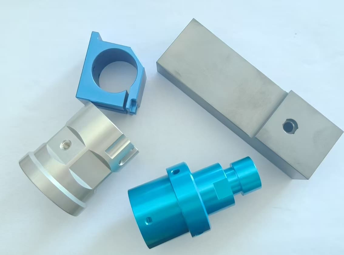
DFM guidelines for semiconductor vacuum CNC parts define critical design rules for high‑precision vacuum CNC machined components, including vacuum chambers, flanges, base plates, gas distribution components, and structural fixtures. These components run inside ultra‑high vacuum (UHV) and cleanroom environments, where even minor manufacturing defects, micro‑leaks, or outgassing contamination can trigger wafer defects, process instability and costly production downtime. Design for Manufacturability (DFM) is a specialized engineering practice that balances strict vacuum performance requirements, CNC machinability, dimensional accuracy, and long‑term operational reliability. This practical DFM guide walks through core design principles, material‑selection rules, structural optimization, tolerance management, surface‑finishing specifications, and frequent design mistakes, helping mechanical and procurement engineers deliver high‑quality, cost‑effective custom CNC aluminum spare parts that satisfy UHV industry standards.
1. Why Specialized DFM Matters for Semiconductor Vacuum CNC Parts
Unlike general‑purpose industrial CNC components, semiconductor vacuum parts carry two non‑negotiable core requirements: zero vacuum leakage and ultra‑low outgassing. Conventional CNC DFM mostly focuses on cost reduction and easy machining; vacuum‑oriented DFM prioritizes vacuum tightness, surface cleanliness, structural stability under negative pressure, and full compatibility with semiconductor clean‑room workflows. Refer to the MIL‑PRF‑8625 specification for baseline industry coating and material reference for vacuum hardware.
Poor DFM for vacuum CNC parts creates recurring field issues: micro‑cracks caused by ill‑conceived geometry, leftover tool marks that trap adsorbed gas, uneven material stress leading to vacuum‑induced deformation, and excessive outgassing that ruins wafer‑processing conditions. Semiconductor industry statistics indicate more than 60 % of vacuum‑system failures originate from design‑driven manufacturing flaws instead of assembly errors. Following tailored DFM guidelines for semiconductor vacuum CNC parts mitigates manufacturability risks at the drawing stage, raises component yield by 30 %‑50 %, cuts post‑processing rework, and extends service life for vacuum hardware deployed inside semiconductor fabs.
2. Material Selection DFM Guidelines for Vacuum CNC Parts
Material performance lays the foundation for reliable vacuum CNC parts. Semiconductor vacuum service calls for raw materials with minimal volatile impurities, good structural stability, favorable CNC machinability, and tolerance for high‑temperature bake‑out. DFM material screening must reject low‑purity feedstock and unsuitable alloys known for high outgassing and particle contamination.
2.1 Preferred Industrial‑Grade Materials
For aluminum vacuum CNC parts such as chambers, support brackets and cover plates, specify 6061‑T6 or 5052 high‑purity aluminum alloys. These grades limit volatile contaminants including lead, zinc and cadmium, deliver consistent microstructure, and keep residual stress low after CNC machining, which lowers outgassing rates under UHV. Avoid recycled aluminum and inferior‑grade alloys with inconsistent impurity profiles.
For stainless‑steel vacuum CNC parts including sealing flanges and precision interface connectors, select 316L or 316LN low‑carbon stainless steel. Reduced‑carbon chemistry prevents carbon precipitation during high‑temperature bake‑out and vacuum operation, protecting against surface pitting and gas emission. Do not specify 303 / 303Se stainless steel; sulfur‑selenium alloying additions produce severe outgassing. Standard 304 and 201 stainless steel are also not recommended for critical vacuum boundaries due to elevated‑risk impurity precipitation.
For high‑conductivity vacuum CNC components, adopt TU1 / TU2 oxygen‑free copper (OFHC C10100 / C10200) to suppress oxidation‑related outgassing while preserving stable electrical‑vacuum performance. Where non‑magnetic high‑strength properties are required, consider titanium alloys Grade 2 / Grade 5 together with appropriate anti‑galling surface lubricants.
2.2 Material DFM Taboos
Do not combine dissimilar material grades within a single vacuum CNC assembly. Mismatched coefficients of thermal expansion create mechanical distortion and sealing gaps when parts undergo vacuum bake‑out. For heat‑treatable alloys, allocate uniform machining stock; uneven allowances produce dimensional drift after stress‑relief cycles. All incoming raw stock should pass impurity verification and stress‑relief processing prior to CNC machining to satisfy semiconductor vacuum cleanliness benchmarks. Request material mill test certificates or compliance documents conforming to ASTM or AMS specifications from your CNC machining supplier.
3. Structural Design DFM Optimization for Vacuum CNC Machinability
Geometry for semiconductor vacuum CNC parts must respect real‑world CNC machining constraints while maintaining vacuum tightness and mechanical rigidity. Poor structural choices cause tool chatter, part deflection, unreachable tool paths, and stagnant dead‑space features that collect contaminants. Applying DFM guidelines for semiconductor vacuum CNC parts at drawing phase avoids most costly later‑stage rework.
3.1 Wall Thickness & Structural Rigidity Standards
Consistent wall thickness represents a core DFM rule for vacuum CNC machined parts. Recommended minimum wall thickness: ≥ 0.8 mm for aluminum vacuum CNC parts; ≥ 1.5 mm for stainless‑steel vacuum CNC parts. Excessively thin walls vibrate and deflect during milling, yielding inconsistent surface roughness and dimensional distortion. Variable wall thickness generates non‑uniform stress distribution; over time under vacuum negative pressure this may induce part warping and micro‑leaks along sealing interfaces.
Restrict oversized deep cavities and narrow grooves. Deep narrow features demand long slender cutting tools prone to chatter and tool breakage, amplifying machining error and total cost. Optimize cavity depth‑to‑width ratios so standard cutting tools can access features with stable cutting loads.
3.2 Corner & Feature Design Rules
All internal inside corners on vacuum CNC parts should incorporate generous fillet radii, minimum R3 mm, to eliminate uncleanable dead corners. Sharp internal inside corners retain burrs and trapped debris; during vacuum operation these contaminants desorb gas and contaminate process environments. Size grooves and pockets around common tool diameters (3 mm, 6 mm, 12 mm) to skip custom special‑tool setups, shorten cycle times and reduce tool‑change‑related variation.
3.3 Hole & Thread DFM Specifications
All mounting holes and sealing holes should sit perpendicular to the machined face, enabling vertical tool entry‑exit and minimizing hole‑wall deflection plus burr formation. For blind threaded holes used in vacuum sealing applications, set engaged thread depth at minimum 1.5 × nominal hole diameter to guarantee reliable thread engagement and resist thread slippage under vacuum loading. Critical note: every blind hole must either include vent holes (Ø ≥ 0.5 mm) or be redesigned as through‑holes to eliminate virtual leaks.
Standardize thread sizes such as M6 and M8. Avoid rare non‑standard thread forms. Keep threads away from part edges and high‑stress zones. Provide sufficient deburring and cleaning clearance for threaded holes to stop metallic chips from falling into vacuum cavities. Add thread‑root relief undercuts to improve internal ventilation.
3.4 Setup Consolidation Design
Minimize CNC set‑ups in your DFM layout. Group functional geometry onto as few machined faces as practical to cut repeated re‑clamping and re‑positioning. Each re‑fixture introduces positioning offset and tolerance stack‑up that directly degrade flatness and sealing performance on vacuum flange surfaces. Monolithic integrated geometries reduce set‑up count, boost dimensional repeatability and strengthen overall vacuum‑system reliability. Avoid dual O‑ring grooves or multi‑layer stacked‑plate layouts that trap enclosed gas volumes and trigger virtual‑leak risks.
Following robust DFM guidelines for semiconductor vacuum CNC parts during design phase can drastically cut fixture‑related errors for complex multi‑surface vacuum components.
4. Tolerance Control DFM Guidelines for Semiconductor Vacuum CNC Parts
Well‑managed dimensional and geometric tolerances define sealing integrity and assembly fit for vacuum CNC machined parts. Over‑loose tolerances produce assembly gaps and micro‑leaks; unnecessarily tight tolerances raise machining difficulty, scrap rate and total cost. Tiered tolerance assignment is essential to balance vacuum performance and commercial feasibility.
4.1 Graded Tolerance Setting
Apply ISO 2768‑m general‑purpose medium tolerances to non‑critical secondary features to contain manufacturing cost. Assign tight dimensional tolerances ± 0.01 mm together with formal GD&T geometric controls for high‑priority vacuum sealing faces, flange mating planes and precision locating holes, ensuring flatness, parallelism and perpendicularity meet strict UHV assembly requirements.
Avoid over‑specified tight tolerances across the whole component. Restrict tight tolerances only to key functional dimensions and relax non‑critical dimensions appropriately. This DFM strategy lowers inspection workload, reduces rework and scrap, while preserving core vacuum‑related performance.
4.2 Tolerance Stack‑Up Avoidance
Take core sealing surfaces and locating datums as primary references when defining tolerances. Distribute dimensional allowances outward layer‑by‑layer to prevent cumulative tolerance errors. Clearly mark inspection datums on engineering drawings, so machining and quality inspection share identical reference benchmarks and eliminate positioning‑based dimensional deviation.
5. Surface Finishing DFM Standards for Ultra‑Low Outgassing
Surface roughness is the key factor affecting vacuum outgassing rate and cleaning performance of semiconductor parts. Rough surfaces form microscopic gaps that adsorb air, moisture, and tiny particles, which slowly release gas in UHV environments and destroy wafer processing purity. DFM must specify zone‑based surface finishing requirements based on functional scenarios.
5.1 Surface Roughness vs. Outgassing Rate Correlation
| Surface Finish | Ra (μm) | Outgassing Rate (Pa·m³/s·m²) | Reference |
|---|---|---|---|
| As‑machined | 3.2 | ~5×10⁻⁸ | |
| Precision machined | 0.8 | ~1×10⁻⁸ | |
| Fine polished | 0.2 | ~5×10⁻⁹ |
Note: Outgassing rates are highly dependent on bake‑out processes. The above data represents un‑baked reference values. After 150–200°C×24h bake, 316L stainless steel H₂ outgassing can be reduced to 3×10⁻¹² mbar·L/s·cm².
5.2 Zone‑Based Surface Requirements
For vacuum cavity inner walls and direct wafer‑contact components, specify Ra ≤0.2μm fine machining and polishing to minimize microscopic adsorption areas. For common assembly and non‑sealing outer surfaces, adopt Ra 0.8μm precision machining to balance performance and cost. Avoid unnecessary ultra‑fine polishing on non‑critical surfaces to reduce processing cycles.
5.3 Post‑Processing DFM Standards
In terms of post‑processing DFM, select vacuum‑compatible treatments such as high‑temperature baking (150–200°C×24–48h), ultrasonic cleaning, electropolishing, and passivation (ASTM A967 for stainless steel). Prohibit ordinary sandblasting and unqualified anodization, which easily produce surface shedding and volatile contaminants. For aluminum parts, Type III hard anodize is acceptable only with proper sealing treatment. All surface treatments must ensure no residual chemical substances to meet semiconductor cleanroom standards. Use water‑soluble synthetic cutting fluids and avoid sulfur‑containing cutting oils.
6. Defect Avoidance & Advanced DFM Best Practices
Many procurement teams overlook how detailed DFM guidelines for semiconductor vacuum CNC parts can reduce sample iteration cycles for new vacuum hardware projects.
6.1 Eliminate Hidden Contamination Structures
Optimize part structures to avoid blind holes, narrow gaps, and stacked steps that are difficult to clean. All internal cavity structures must be designed with cleaning and ventilation channels to ensure thorough removal of CNC cutting fluid, metal debris, and surface impurities. Residual contaminants are the main cause of long‑term outgassing and vacuum system failure.
6.2 Residual Stress Control
Arrange rough machining, stress relief annealing, and finish machining processes reasonably in DFM design. Remove machining residual stress through low‑temperature stress relief treatment to prevent slow deformation of parts in long‑term vacuum and temperature cycling environments, which leads to sealing failure and dimensional drift.
6.3 Standardization & Modular Design
Adopt modular DFM design for universal semiconductor vacuum parts such as flanges and connectors. Standardize feature sizes, hole positions, and structural specifications to improve part compatibility, reduce customized processing costs, and simplify subsequent assembly and maintenance. Modular design also unifies machining tool paths and tolerance standards, significantly improving batch production yield and consistency.
7. Conclusion
DFM guidelines for semiconductor vacuum CNC parts are a systematic engineering system covering material selection, structural optimization, tolerance control, surface finishing, and process matching. Different from ordinary CNC DFM, vacuum semiconductor part design takes ultra‑low outgassing, zero micro‑leakage, and clean compatibility as the core, realizing the perfect unity of machinability, operational reliability, and cost efficiency.
By following the above DFM rules—selecting qualified low‑outgassing materials, optimizing structural machinability and rigidity, grading precision tolerances, standardizing vacuum‑level surface finishing, and avoiding contamination and stress defects—engineers can effectively improve the manufacturing quality of semiconductor vacuum CNC parts, reduce rework and failure rates, and provide stable and reliable component support for high‑end semiconductor wafer processing, etching, and deposition processes. In the increasingly stringent semiconductor manufacturing environment, standardized vacuum CNC DFM design has become a key factor in improving production yield and equipment stability.
Appendix: DFM Checklist for Semiconductor Vacuum CNC Parts
Target Users: Design Engineers, Procurement Engineers, CNC Machining Suppliers
- Materials & Sealing
- Structural materials: 304L/316L stainless steel or 6061‑T6 aluminum (prohibit 303 stainless steel)
- CF flange seals: Specify annealed OFHC copper gaskets
- Polymers (if required): Provide ASTM E595 outgassing data
- Virtual Leak Prevention
- Convert all blind holes to through‑holes or add vent holes (Ø≥0.5mm)
- Add thread relief/undercut at root for ventilation
- Avoid double O‑ring grooves or stacked plate trapped volumes
- Machining Requirements
- Vacuum contact surfaces: Ra ≤1.6μm (pre‑treatment), sealing surfaces Ra ≤0.2μm
- Specify electropolishing (if lower outgassing required)
- Prohibit sulfur‑containing cutting oils; use water‑soluble synthetic cutting fluids
- Cleaning & Bake‑Out
- Alkaline cleaner + hot DI water rinse until water‑break free
- Solvent clean (acetone/IPA, reagent grade) + DI rinse + N₂ blow dry
- Vacuum bake: Stainless steel 150–200°C×24–48h; aluminum at reduced temperature
- Inspection & Testing
- Visual inspection: No tool marks on knife edges, no damage on sealing surfaces
- Helium mass spectrometer leak test: ≤1×10⁻¹⁰ mbar·L/s (UHV interfaces)
- Virtual leak check: No slow pressure decay in hold curve